|
CIM++ Adapted CIM_SINERGIEN Codebase
|
#include <TopologicalNode.h>
Public Attributes | |
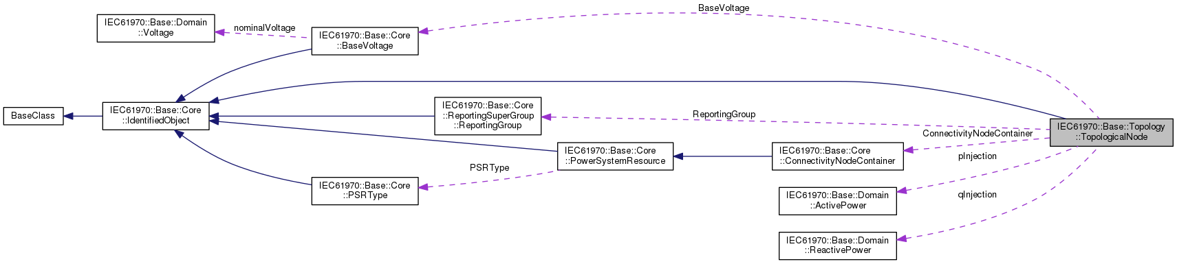
| IEC61970::Base::Domain::ActivePower | pInjection |
| IEC61970::Base::Domain::ReactivePower | qInjection |
| IEC61970::Base::Core::ReportingSuperGroup::ReportingGroup * | ReportingGroup |
| IEC61970::Base::Core::ConnectivityNodeContainer * | ConnectivityNodeContainer |
| std::list< IEC61970::Base::Core::ConnectivityNode * > | ConnectivityNodes |
| IEC61970::Base::Core::BaseVoltage * | BaseVoltage |
| std::list< IEC61970::Base::Core::Terminal * > | Terminal |
 Public Attributes inherited from IEC61970::Base::Core::IdentifiedObject Public Attributes inherited from IEC61970::Base::Core::IdentifiedObject | |
| IEC61970::Base::Domain::String | aliasName |
| IEC61970::Base::Domain::String | description |
| IEC61970::Base::Domain::String | mRID |
| IEC61970::Base::Domain::String | name |
| std::list< IEC61970::Base::DiagramLayout::DiagramObject * > | DiagramObjects |
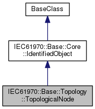
For a detailed substation model a topological node is a set of connectivity nodes that, in the current network state, are connected together through any type of closed switches, including jumpers. Topological nodes change as the current network state changes (i.e., switches, breakers, etc. change state). For a planning model, switch statuses are not used to form topological nodes. Instead they are manually created or deleted in a model builder tool. Topological nodes maintained this way are also called "busses".
| IEC61970::Base::Core::BaseVoltage* IEC61970::Base::Topology::TopologicalNode::BaseVoltage |
The base voltage of the topologocial node.
| IEC61970::Base::Core::ConnectivityNodeContainer* IEC61970::Base::Topology::TopologicalNode::ConnectivityNodeContainer |
The connectivity node container to which the toplogical node belongs.
| std::list<IEC61970::Base::Core::ConnectivityNode*> IEC61970::Base::Topology::TopologicalNode::ConnectivityNodes |
The connectivity nodes combine together to form this topological node. May depend on the current state of switches in the network.
| IEC61970::Base::Domain::ActivePower IEC61970::Base::Topology::TopologicalNode::pInjection |
The active power injected into the bus at this location in addition to injections from equipment. Positive sign means injection into the TopologicalNode (bus). Starting value for a steady state solution.
| IEC61970::Base::Domain::ReactivePower IEC61970::Base::Topology::TopologicalNode::qInjection |
The reactive power injected into the bus at this location in addition to injections from equipment. Positive sign means injection into the TopologicalNode (bus). Starting value for a steady state solution.
| IEC61970::Base::Core::ReportingSuperGroup::ReportingGroup* IEC61970::Base::Topology::TopologicalNode::ReportingGroup |
The reporting group to which the topological node belongs.
| std::list<IEC61970::Base::Core::Terminal*> IEC61970::Base::Topology::TopologicalNode::Terminal |
The terminals associated with the topological node. This can be used as an alternative to the connectivity node path to terminal, thus making it unneccesary to model connectivity nodes in some cases. Note that if connectivity nodes are in the model, this association would probably not be used as an input specification.
 1.8.11

