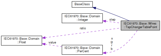

| IEC61970::Base::Domain::PerCent IEC61970::Base::Wires::TapChangerTablePoint::b |
The magnetizing branch susceptance deviation in percent of nominal value. The actual susceptance is calculated as follows: calculated magnetizing susceptance = b(nominal) * (1 + b(from this class)/100). The b(nominal) is defined as the static magnetizing susceptance on the associated power transformer end or ends. This model assumes the star impedance (pi model) form.
| IEC61970::Base::Domain::PerCent IEC61970::Base::Wires::TapChangerTablePoint::g |
The magnetizing branch conductance deviation in percent of nominal value. The actual conductance is calculated as follows: calculated magnetizing conductance = g(nominal) * (1 + g(from this class)/100). The g(nominal) is defined as the static magnetizing conductance on the associated power transformer end or ends. This model assumes the star impedance (pi model) form.
| IEC61970::Base::Domain::PerCent IEC61970::Base::Wires::TapChangerTablePoint::r |
The resistance deviation in percent of nominal value. The actual reactance is calculated as follows: calculated resistance = r(nominal) * (1 + r(from this class)/100). The r(nominal) is defined as the static resistance on the associated power transformer end or ends. This model assumes the star impedance (pi model) form.
| IEC61970::Base::Domain::Float IEC61970::Base::Wires::TapChangerTablePoint::ratio |
The voltage at the tap step divided by rated voltage of the transformer end having the tap changer. Hence this is a value close to one. For example, if the ratio at step 1 is 1.01, and the rated voltage of the transformer end is 110kV, then the voltage obtained by setting the tap changer to step 1 to is 111.1kV.
| IEC61970::Base::Domain::Integer IEC61970::Base::Wires::TapChangerTablePoint::step |
The tap step.
| IEC61970::Base::Domain::PerCent IEC61970::Base::Wires::TapChangerTablePoint::x |
The series reactance deviation in percent of nominal value. The actual reactance is calculated as follows: calculated reactance = x(nominal) * (1 + x(from this class)/100). The x(nominal) is defined as the static series reactance on the associated power transformer end or ends. This model assumes the star impedance (pi model) form.
 1.8.13