
|
IEC61970 16v29a - SINERGIEN 20170705
|

|
|
|
IEC61970 16v29a - SINERGIEN 20170705
|
|
#include <StaticVarCompensator.h>
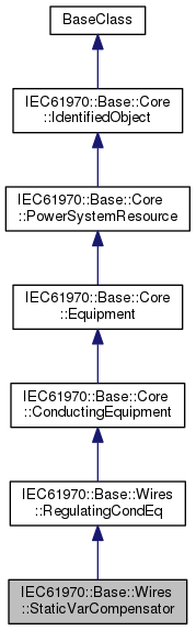
A facility for providing variable and controllable shunt reactive power. The SVC typically consists of a stepdown transformer, filter, thyristor-controlled reactor, and thyristor-switched capacitor arms.
The SVC may operate in fixed MVar output mode or in voltage control mode. When in voltage control mode, the output of the SVC will be proportional to the deviation of voltage at the controlled bus from the voltage setpoint. The SVC characteristic slope defines the proportion. If the voltage at the controlled bus is equal to the voltage setpoint, the SVC MVar output is zero.
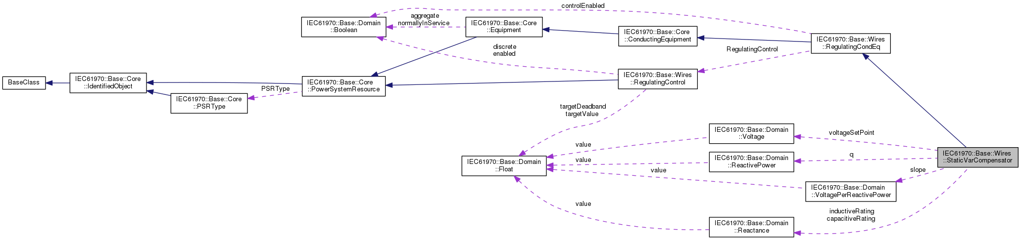
| IEC61970::Base::Domain::Reactance IEC61970::Base::Wires::StaticVarCompensator::capacitiveRating |
Maximum available capacitive reactance.
| IEC61970::Base::Domain::Reactance IEC61970::Base::Wires::StaticVarCompensator::inductiveRating |
Maximum available inductive reactance.
| IEC61970::Base::Domain::ReactivePower IEC61970::Base::Wires::StaticVarCompensator::q |
Reactive power injection. Load sign convention is used, i.e. positive sign means flow out from a node. Starting value for a steady state solution.
| IEC61970::Base::Domain::VoltagePerReactivePower IEC61970::Base::Wires::StaticVarCompensator::slope |
The characteristics slope of an SVC defines how the reactive power output changes in proportion to the difference between the regulated bus voltage and the voltage setpoint.
| IEC61970::Base::Wires::SVCControlMode IEC61970::Base::Wires::StaticVarCompensator::sVCControlMode = IEC61970::Base::Wires::SVCControlMode::_undef |
SVC control mode.
| IEC61970::Base::Domain::Voltage IEC61970::Base::Wires::StaticVarCompensator::voltageSetPoint |
The reactive power output of the SVC is proportional to the difference between the voltage at the regulated bus and the voltage setpoint. When the regulated bus voltage is equal to the voltage setpoint, the reactive power output is zero.
 1.8.13
 Public Attributes inherited from