
|
IEC61970 16v29a - SINERGIEN 20170705
|

|
|
|
IEC61970 16v29a - SINERGIEN 20170705
|
|
#include <PowerTransformer.h>
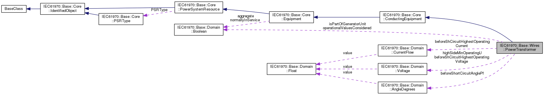
An electrical device consisting of two or more coupled windings, with or without a magnetic core, for introducing mutual coupling between electric circuits. Transformers can be used to control voltage and phase shift (active power flow). A power transformer may be composed of separate transformer tanks that need not be identical. A power transformer can be modeled with or without tanks and is intended for use in both balanced and unbalanced representations. A power transformer typically has two terminals, but may have one (grounding), three or more terminals. The inherited association ConductingEquipment.BaseVoltage should not be used. The association from TransformerEnd to BaseVoltage should be used instead.
| IEC61970::Base::Domain::CurrentFlow IEC61970::Base::Wires::PowerTransformer::beforeShCircuitHighestOperatingCurrent |
The highest operating current (Ib in the IEC 60909-0) before short circuit (depends on network configuration and relevant reliability philosophy). It is used for calculation of the impedance correction factor KT defined in IEC 60909- 0.
| IEC61970::Base::Domain::Voltage IEC61970::Base::Wires::PowerTransformer::beforeShCircuitHighestOperatingVoltage |
The highest operating voltage (Ub in the IEC 60909-0) before short circuit. It is used for calculation of the impedance correction factor KT defined in IEC 60909-0. This is worst case voltage on the low side winding (Section 3.7.1 in the standard). Used to define operating conditions.
| IEC61970::Base::Domain::AngleDegrees IEC61970::Base::Wires::PowerTransformer::beforeShortCircuitAnglePf |
The angle of power factor before short circuit (phib in the IEC 60909-0). It is used for calculation of the impedance correction factor KT defined in IEC 60909- 0. This is the worst case power factor. Used to define operating conditions.
| IEC61970::Base::Domain::Voltage IEC61970::Base::Wires::PowerTransformer::highSideMinOperatingU |
The minimum operating voltage (uQmin in the IEC 60909-0) at the high voltage side (Q side) of the unit transformer of the power station unit. A value well established from long-term operating experience of the system. It is used for calculation of the impedance correction factor KG defined in IEC 60909-0
| IEC61970::Base::Domain::Boolean IEC61970::Base::Wires::PowerTransformer::isPartOfGeneratorUnit |
Indicates whether the machine is part of a power station unit. Used for short circuit data exchange according to IEC 60909
| IEC61970::Base::Domain::Boolean IEC61970::Base::Wires::PowerTransformer::operationalValuesConsidered |
It is used to define if the data (other attributes related to short circuit data exchange) defines long term operational conditions or not. Used for short circuit data exchange according to IEC 60909.
| std::list<IEC61970::Base::Wires::PowerTransformerEnd*> IEC61970::Base::Wires::PowerTransformer::PowerTransformerEnd |
The ends of this power transformer.
| IEC61970::Base::Domain::String IEC61970::Base::Wires::PowerTransformer::vectorGroup |
Vector group of the transformer for protective relaying, e.g., Dyn1. For unbalanced transformers, this may not be simply determined from the constituent winding connections and phase angle dispacements.
The vectorGroup string consists of the following components in the order listed: high voltage winding connection, mid voltage winding connection (for three winding transformers), phase displacement clock number from 0 to 11, low voltage winding connection phase displacement clock number from 0 to 11. The winding connections are D (delta), Y (wye), YN (wye with neutral), Z (zigzag), ZN (zigzag with neutral), A (auto transformer). Upper case means the high voltage, lower case mid or low. The high voltage winding always has clock postion 0 and is not included in the vector group string. Some examples: YNy0 (two winding wye to wye with no phase displacement), YNd11 (two winding wye to delta with 330 degrees phase displacement), YNyn0d5 (three winding transformer wye with neutral high voltgage, wye with neutral mid voltgage and no phase displacement, delta low voltage with 150 degrees displacement).
Phase displacement is defined as the angular difference between the phasors representing the voltages between the neutral point (real or imaginary) and the corresponding terminals of two windings, a positive sequence voltage system being applied to the high-voltage terminals, following each other in alphabetical sequence if they are lettered, or in numerical sequence if they are numbered: the phasors are assumed to rotate in a counter-clockwise sense.
 1.8.13
 Public Attributes inherited from